


Networking & Wireless · Structured Cabling
Cable Test Report: 5 Essential Results Explained
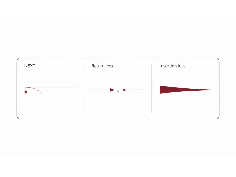
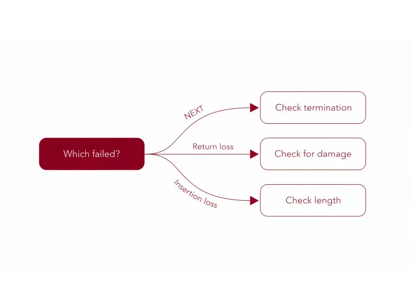
A cable test report tells you more than pass or fail. Which parameter failed narrows the cause to a handful of possibilities, and the combination of what passed alongside it usually identifies the fault outright. A NEXT failure points at the termination. A return loss failure points at damage or mismatched components. An insertion loss failure usually points at length.
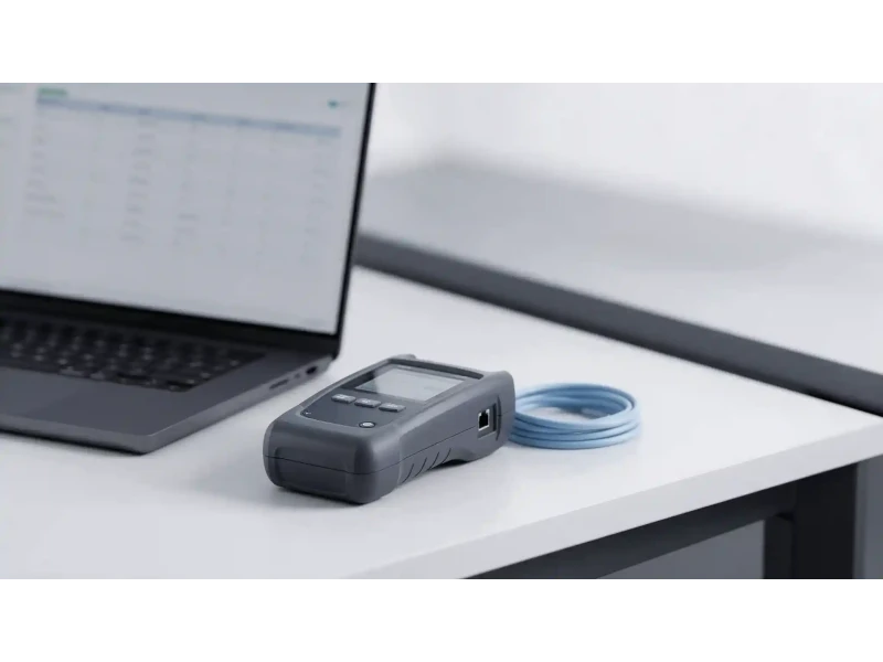
Key takeaways
- Margin matters more than the verdict. A link passing by 0.4 dB and one passing by 8 dB are both a pass, and only one of them is safe.
- NEXT failures are almost always installation, not product. Excessive untwist at the termination is the single most common cause.
- Return loss points at physical damage or mismatched components — a kink, a crush, or a Cat5e jack on Cat6A cable.
- Insertion loss usually means length. If the length test is also marginal, that is your answer.
- The pattern of what passed alongside the failure narrows the cause faster than the failure alone.
- Check the test setup before re-terminating anything. Wrong standard selected, wrong adapter or a worn reference lead produce real failures on good cable.
What a cable test report should contain
Before interpreting results, confirm the report is complete. A certification report that omits any of these is difficult to rely on, and impossible to submit for a manufacturer warranty.
| Field | Why it matters |
|---|---|
| Cable ID | Ties the result to a physical link. Without it the report is unusable for remediation. |
| Standard tested against | Category and link type. A Cat6A cable tested to a Cat6 standard will pass and prove nothing. |
| Link type | Permanent link or channel. Different limits apply. |
| Instrument and accuracy level | A result from a tester below the required accuracy level is not a valid certification. |
| Calibration date | An out-of-calibration instrument invalidates every result in the batch. |
| Per-parameter results with margin | The verdict alone hides how close a link came to failing. |
| Date and technician | Traceability if results are later disputed. |
Pass, fail, and the asterisk
Three verdicts appear on a typical report, and the third causes the most confusion.
PASS
Every measured parameter sits within the standard's limit with margin to spare. Note the worst-case margin anyway — it is the number that predicts future behaviour.
PASS*
Passed, but at least one result sits within the instrument's measurement uncertainty of the limit. Technically a pass; practically a link with almost no headroom.
FAIL
At least one parameter is outside the limit. Which one, and what passed alongside it, is what tells you where to look.
On a commercial project, treat every asterisk as something to investigate. A marginal pass today has no tolerance left for the things that erode margin later: a longer patch cord added during a move, a warmer plant room in August, connector wear over years of re-patching.
The practical example is a run measured at 88 metres. That is inside the 90-metre permanent link limit, so it passes. But it leaves almost nothing for the patch cords that will be added at both ends, and our guide to Ethernet cable distance limits explains why the channel budget is what actually matters. Worth flagging on the report, not celebrating as a pass.
NEXT failures
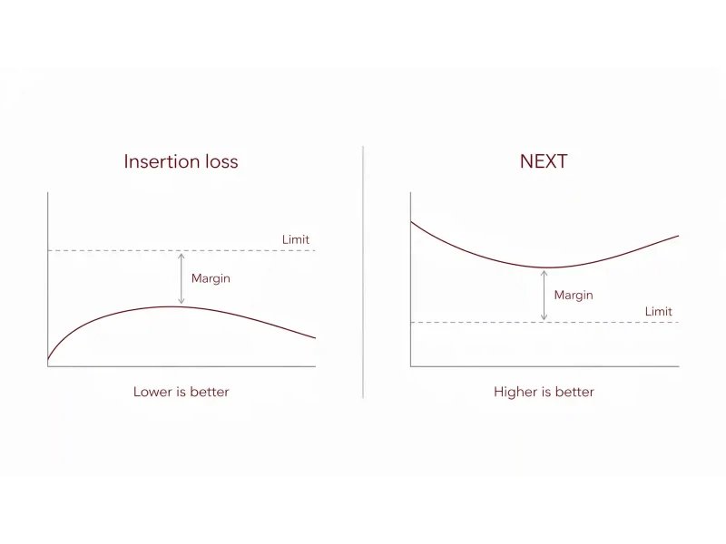
Near-end crosstalk measures signal coupling from one pair into another, measured at the same end the signal was injected. PS-NEXT is the summed effect of all other pairs on one pair. Higher dB values are better — they mean less coupling.
A NEXT failure is an installation problem far more often than a product problem. The dominant cause is excessive untwisting of the pairs at the termination. The twist is what cancels crosstalk; unwinding it for convenience during punch-down removes that cancellation exactly where the pairs are closest together.
Common guidance is to keep untwist to roughly 13 mm — about half an inch — at the connector, and manufacturers frequently specify tighter limits for higher categories. Check the figure for the components actually being installed.
Causes, in rough order of likelihood:
- Excessive untwist at the jack or plug — by a wide margin the most common
- Compression from over-tightened cable ties or aggressive bundling, which deforms pair geometry along the run
- Split pairs — electrically continuous, wire map may pass, crosstalk badly degraded
- Couplers used inappropriately in the link
- Component quality or category mismatch — the right cable terminated into the wrong jack
The fix for the common case is straightforward and cheap: cut back, re-strip, and re-terminate with proper pair management, keeping the twist as close to the contact as the connector allows. Then re-test.
Return loss failures
Return loss measures how much signal is reflected back toward the transmitter by impedance discontinuities. Twisted pair cabling is nominally 100 ohms; anywhere the impedance deviates, part of the signal bounces. Higher dB is better — it means less reflected energy.
A return loss failure points at physical damage or a component mismatch, and it is the parameter most sensitive to how the cable was handled.
- Kinked or crushed cable — a tight bend, a staple, a cable pinched above a ceiling tile
- Mixed component categories — a Cat5e jack terminating Cat6A cable creates a discontinuity at the connector
- Poor or damaged terminations, or poorly matched plug and jack combinations
- Mishandled patch cords — cords that have been crushed, over-bent or repeatedly yanked
- Cable whose impedance is not uniform along its length, which points at product quality
One useful caution from the field: kinks and knots do not always produce a failure, particularly with good quality cable. An absence of return loss failures is not proof that the installation was handled well.
Insertion loss failures
Insertion loss — attenuation — is simply how much signal is lost along the link. Unlike NEXT and return loss, lower dB is better here, and the cause list is short.
- The link is too long. If the length result is also marginal or failing, you have your answer.
- Wrong category of cable for the standard being tested against.
- Poor-quality or non-twisted patch cords in a channel test.
- High-impedance connections — a poor termination adding resistance.
- Cable that does not actually meet its marked specification. Copper-clad aluminium sold as copper is the classic case, and our guide to cable construction and specification covers why marked category is not the same as verified performance.
Temperature also matters and is easy to overlook. Insertion loss rises with temperature, so a link tested in a cool morning plant room can measure differently in August. A link with minimal insertion loss margin in a hot environment is worth re-examining rather than accepting.
Reading the failure pattern
This is where a report becomes genuinely diagnostic. What passed alongside the failure usually narrows the cause to one or two possibilities.
| Pattern | Most likely cause | First action |
|---|---|---|
| NEXT fails, length and insertion loss pass | Excessive untwist at a termination | Re-terminate both ends, re-test |
| Return loss fails, NEXT passes | Physical damage near a connector, or mixed component categories | Check the TDR plot for fault location |
| Insertion loss fails, NEXT and return loss pass | Run too long, or cable not meeting its marked specification | Verify length, then verify the cable |
| Insertion loss and return loss both fail | Run substantially over the limit | Re-route, or add an intermediate switch |
| ACR-F fails on long runs, passes on short runs of the same batch | Marginal intrinsic cable quality | Replace the cable |
| Delay skew fails, everything else passes | Mixed cable batches within one run, or severely deformed cable | Replace; do not mix batches in a run |
| Everything fails, wildly | Wrong standard or wrong adapter selected | Check the test setup before touching the cable |
Locating the fault
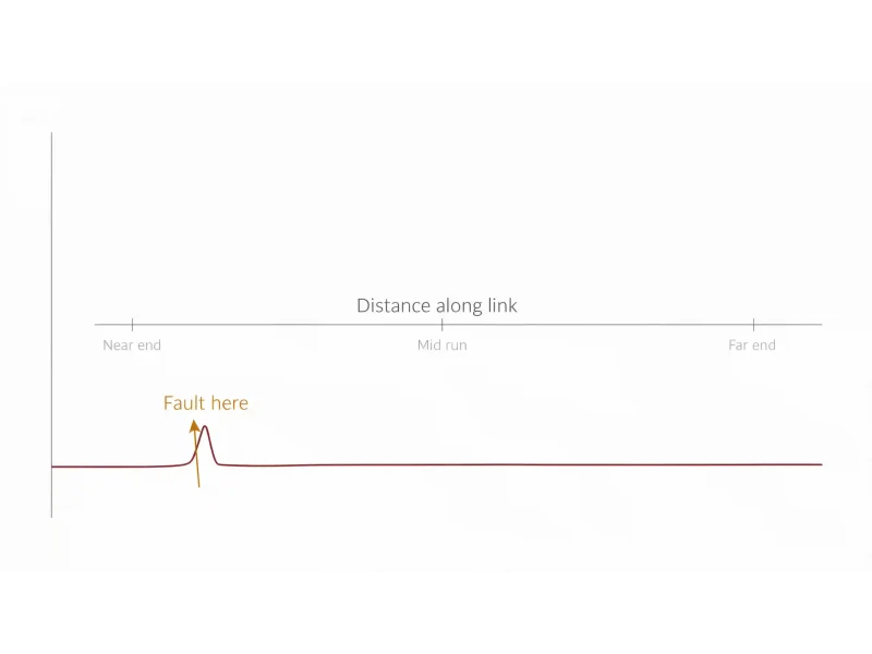
Knowing a link fails NEXT is useful. Knowing it fails NEXT 17 metres from the remote end is actionable.
Certification testers include time-domain diagnostics that plot crosstalk and reflection against distance along the link, showing where along the cable the problem originates. A spike at the very start of the plot indicates the near-end termination. A spike at the far end indicates the other termination. A spike in the middle indicates damage along the run — a crush point, a staple, a tight bend behind a wall.
This turns a failing link from a search into a visit. Where a fault sits within the first couple of metres, the cause is almost always the jack or the patch cord at that end, and replacing a suspect patch cord is the fastest test of that hypothesis.
Read the distance on the diagnostic plot
Note where the spike sits relative to the total link length before going anywhere.
If it is at either extreme, suspect the termination
Near-end or far-end spikes point at the jack, plug or patch cord at that end.
Swap the patch cord first
Cheapest and fastest hypothesis to eliminate on a channel test. A damaged cord explains a surprising share of failures.
Re-terminate if the fault stays
Cut back, re-strip and re-punch with minimal untwist. Re-test immediately rather than batching.
If a fault repeats on one jack across cables, replace the jack
A consistent failure at the same component across multiple links points at that component, not the cable.
Mid-run faults mean physical inspection
Something is compressing or bending the cable at that distance. Re-terminating will not help.
Before you blame the cable
A meaningful share of certification failures are not cable failures at all. Check these before anyone starts cutting.
Wrong standard selected
Testing Cat6 cable against a Cat6A limit line produces failures on perfectly good installation. Confirm the autotest matches what was installed.
Wrong or worn link adapter
Permanent link and channel tests use different adapters. A worn adapter or reference lead introduces error across every test taken that day.
Electrical noise nearby
Testing beside running machinery, VFDs or heavy switchgear can produce crosstalk readings that have nothing to do with the cabling.
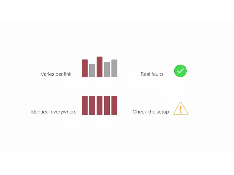
If a whole batch of links fails identically, the setup is the first suspect, not the installation. Genuine installation faults vary between links because terminations vary between links.
Frequently asked questions
What does PASS with an asterisk mean on a cable test report?
It means the link passed, but at least one measurement sits within the instrument's measurement uncertainty of the limit. It is technically a pass with effectively no headroom. On commercial projects marginal results should be flagged and investigated, because anything that erodes margin later — a longer patch cord, higher temperature, connector wear — can push the link into failure.
What causes a NEXT failure?
Most often excessive untwisting of the pairs at the termination, since the twist is what cancels crosstalk. Other causes include compression from over-tightened cable ties, split pairs, inappropriate couplers, and mismatched or poor-quality components. It is an installation problem far more often than a product problem.
What causes a return loss failure?
Impedance discontinuities. In practice that means kinked or crushed cable, mixed component categories such as a Cat5e jack on Cat6A cable, damaged or poorly matched terminations, or mishandled patch cords. The time-domain plot on a certification tester shows where along the link the reflection occurs.
What causes an insertion loss failure?
Usually excessive length — if the length result is also marginal, that is the answer. Other causes are the wrong category of cable for the standard tested, poor-quality patch cords, high-impedance connections, or cable that does not meet its marked specification. Insertion loss also rises with temperature.
Can a link fail certification and still carry traffic?
Yes. Certification measures margin against a standard rather than whether traffic passes today. A link failing on crosstalk or return loss may run current applications acceptably and then fail when equipment is upgraded, temperature changes, or connectors age. That margin is what the standard and the warranty are protecting.
Should I re-terminate immediately when a link fails?
Check the test setup first. Wrong standard selected, wrong or worn link adapter, or electrical noise nearby all produce genuine failures on good cabling. If an entire batch fails identically, the setup is the likely cause — real installation faults vary from link to link.
How much untwist is acceptable at a termination?
Commonly cited guidance is around 13 mm, roughly half an inch, at the connector. Manufacturers frequently specify tighter limits for higher categories, so check the figure for the specific components being installed rather than applying one number universally.
What does the diagnostic distance plot tell me?
It shows where along the link a crosstalk or reflection problem originates. A spike at the start or end points at that termination; a spike in the middle points at physical damage along the run, such as a crush point or tight bend. That converts a failing result into a specific location to inspect.
Fixing the causes before they reach the report
Most of what appears on a failing report was decided long before the tester was connected — an over-length run, a mismatched jack, cable that did not meet its marked specification, or a termination rushed at the end of a shift.
Magnus supplies Premium-Line structured cabling, keystone jacks and patch panels as matched component sets across our networking and wireless solutions range. Tell us the standard the installation has to certify to and our pre-sales team will specify components that will get there.
Get a quoteSource
Performance limits for copper cabling are defined in ANSI/TIA-568 and ISO/IEC 11801, with exact values varying by category and by link type (permanent link or channel). Field tester accuracy levels are defined in ANSI/TIA-1152. The failure causes and diagnostic patterns described here are drawn from published field test instrument manufacturer troubleshooting guidance and independent cabling industry technical references, cross-checked across multiple sources. The untwist figure is given as commonly cited general guidance; component manufacturers specify their own limits, frequently tighter for higher categories, and those take precedence. Reported values depend on the standard selected, the link configuration, the instrument and its calibration state, and environmental conditions at the time of test.